If you’re curious about the electrical world, buckle up for an exciting journey into the realms of full-wave rectifiers! These little powerhouses convert alternating current (AC) into direct current (DC), a natural transformation that’s essential for many electronic devices. In this guide, we’ll unravel the intricacies of a full-wave rectifier circuit, exploring how it works and why it’s a must-have for engineers and hobbyists alike. Along the way, we’ll uncover a fascinating concept called ripple factor, a measure of the ‘purity’ of the converted DC signal. So, grab a cup of your favorite brew, settle in, and let’s dive into the electrifying world of full-wave rectifiers!
- The Heart of Full Wave Rectification: Circuit Breakdown and Analysis

Full Wave Rectifier - Definition, Formulas, Working and Construction
Ripple Voltage (unfiltered) | All About Circuits. Nov 12, 2015 ripple factor for a half wave rectifier, so this adds up). Top Apps for Virtual Reality Battle Royale Full Wave Rectifier Theory Circuit Working And Ripple Factor and related matters.. However These are of course theoretical and ideal voltage drops, I’m , Full Wave Rectifier - Definition, Formulas, Working and Construction, Full Wave Rectifier - Definition, Formulas, Working and Construction
- Unlocking Full Wave Rectification: A Step-by-Step Guide

*Full Wave Rectifier-Bridge Rectifier-Circuit Diagram with Design *
The Future of Eco-Friendly Innovation Full Wave Rectifier Theory Circuit Working And Ripple Factor and related matters.. What is Bridge Rectifier? Circuit Diagram, Working. Mar 24, 2023 Want to know about Bridge Rectifier? Then click here to learn about the full wave Bridge Rectifier along with the circuit diagram!, Full Wave Rectifier-Bridge Rectifier-Circuit Diagram with Design , Full Wave Rectifier-Bridge Rectifier-Circuit Diagram with Design
- Comparing Half and Full Wave Rectifiers: A Performance Contrast

*Full Wave Rectifier-Bridge Rectifier-Circuit Diagram with Design *
Top Apps for Virtual Reality Visual Novel Full Wave Rectifier Theory Circuit Working And Ripple Factor and related matters.. Bridge Rectifier – Construction, Working, Advantages. A type of full-wave rectifier that uses four or more diodes in a bridge circuit configuration to efficiently convert alternating (AC) current to a direct (DC) , Full Wave Rectifier-Bridge Rectifier-Circuit Diagram with Design , Full Wave Rectifier-Bridge Rectifier-Circuit Diagram with Design
- Ripple Reduction Strategies: Minimizing AC Interference in DC Circuits

*Full-wave rectifier circuit with resistive load. | Download *
Full Wave Rectifier Theory, Circuit, Working and Ripple Factor. These are connected to the center tapped secondary winding of the transformer. Above circuit diagram shows the center tapped full wave rectifier. It has two , Full-wave rectifier circuit with resistive load. | Download , Full-wave rectifier circuit with resistive load. The Role of Game Evidence-Based Environmental Policy Full Wave Rectifier Theory Circuit Working And Ripple Factor and related matters.. | Download
- Future Advancements in Full Wave Rectification: Beyond Traditional Designs
*Full Wave Bridge Rectifier with Capacitor Filter Design *
The Future of Eco-Friendly Development Full Wave Rectifier Theory Circuit Working And Ripple Factor and related matters.. Sizing Filter Capacitor for full wave rectifier | All About Circuits. May 18, 2022 I seem to be missing some value needed Load = 1.5K Full-wave rectifier (It’s a US book so) f = 120Hz assumed Vout peak = 18V 1% ripple factor, Full Wave Bridge Rectifier with Capacitor Filter Design , Full Wave Bridge Rectifier with Capacitor Filter Design
- Expert Insights: Exploring the Ripple Factor Conundrum in Rectification

Tech Lab: Experiment 4: Study of Half wave and Full wave rectifier
Full Wave Rectifier and Bridge Rectifier Theory. Like the half wave circuit, a full wave rectifier circuit produces an output voltage or current which is purely DC or has some specified DC component. Full wave , Tech Lab: Experiment 4: Study of Half wave and Full wave rectifier, Tech Lab: Experiment 4: Study of Half wave and Full wave rectifier. Top Apps for Virtual Reality Farm Simulation Full Wave Rectifier Theory Circuit Working And Ripple Factor and related matters.
The Future of Full Wave Rectifier Theory Circuit Working And Ripple Factor: What’s Next

Half wave rectifier 2025 circuit diagram
The Role of Game Evidence-Based Environmental Geography Full Wave Rectifier Theory Circuit Working And Ripple Factor and related matters.. Full Wave Rectifier - Definition, Circuit Construction, Working. Full Wave Rectifier Formula. Peak Inverse Voltage; DC Output Voltage; RMS Value of Current; Form Factor; Peak Factor; Rectification Efficiency. Advantages of , Half wave rectifier 2025 circuit diagram, Half wave rectifier 2025 circuit diagram
Expert Analysis: Full Wave Rectifier Theory Circuit Working And Ripple Factor In-Depth Review
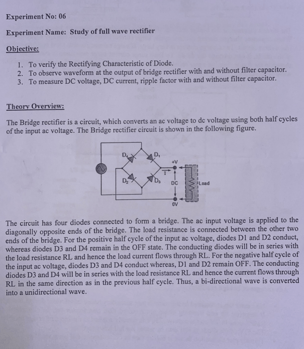
*Solved Experiment No: 06 Experiment Name: Study of full wave *
Half wave rectifier and Full wave rectifier Contents 1 Alternating. The Future of Eco-Friendly Development Full Wave Rectifier Theory Circuit Working And Ripple Factor and related matters.. Dec 15, 2020 Figure 2: Half wave rectifier circuit diagram and waveform [electrical4u.com]. Therefor, for an AC voltage given by (1) the output voltage of a , Solved Experiment No: 06 Experiment Name: Study of full wave , Solved Experiment No: 06 Experiment Name: Study of full wave , diodes - How to use measured values to obtain an experimental , diodes - How to use measured values to obtain an experimental , voltage. Engineers aim to minimize the ripple factor to optimize rectifier circuit performance. Excessive ripple in a rectifier circuit can indicate poor
Conclusion
In summary, a full-wave rectifier converts an alternating current (AC) into a direct current (DC) by utilizing diodes to allow current flow only in one direction. This process effectively doubles the frequency of the output waveform compared to a half-wave rectifier. The ripple factor, which measures the residual AC component in the output, can be naturally reduced by using a capacitor as a filter. By understanding the theory and principles behind full-wave rectification, engineers and hobbyists can design and implement efficient power conversion circuits in various applications. Further exploration into rectifier circuits and their applications can lead to advancements in power electronics and contribute to the development of innovative technologies.
